by Rodney Howe, email ahowe at frii dot com
Circuit Description:
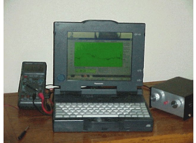
I built the Gyrator II (on the right in the photo below) a couple years ago, when Art Stokes was still alive. He sent me the electrolytic capacitors that I couldn't find anywhere else. All the other parts I found at Radio Shack, including their Digital Multi-Meter, which I use to record on a Laptop. The power supply in the Gyrator II is a split transformer, as outlined in Art Stokes schematics. I made a few modifications to Art's design: I'm using two 10 turn pots as gain and tuning control, this makes it easier to tune the receiver, and adjust the gain.
| Figure 1 Digital Multi-Meter, Panasonic 486 Laptop, Gyrator II
(Click on thumbnail to download full-size image) |
 |
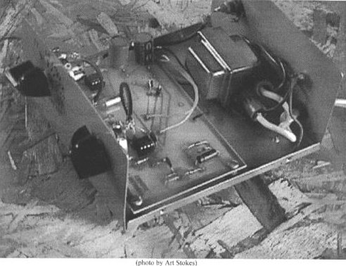
| Figure 1.1 Art Stokes photo of the Gyrator II Courtesy of <http://www.aavso.org/committees/solar/equipment.stm> (Click on thumbnail to download full-size image) |
 |
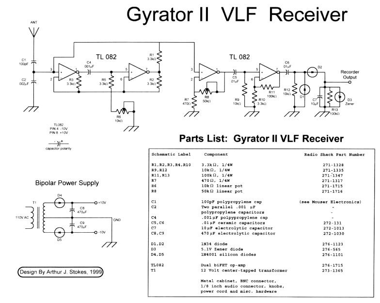
| Figure 1.2 Schematic of Art Stoke's Gyrator II Courtesy of <http://www.aavso.org/committees/solar/equipment.stm> (Click on thumbnail to download full-size image) |
 |
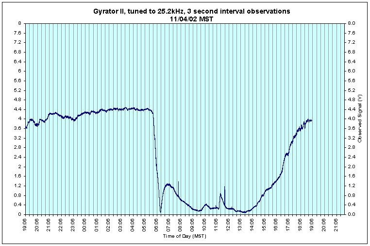
I capture data on a daily basis at 3 second intervals. The Radio Shack DMM writes to flat ASCII file format under a Windows 95 operating system, and I bring these daily data files into an Excel spreadsheet. That way I can make graphs and plots that look similar to the Rustrack recordings.
| Figure 2, November 4 SID
(Click on thumbnail to download full-size image) |
 |
| Figure 3, November 8 SID
(Click on thumbnail to download full-size image) |
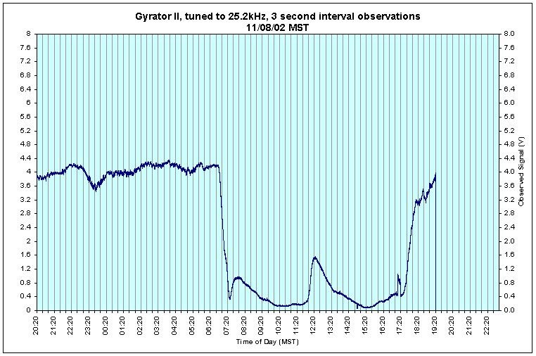 |
All the output from the Gyrator II is presently being captured in voltages, by the DMM. The Gyrator II and the loop antenna (described below) are tuned to 25.2kHz, the VLF transmitter in North Dakota. The receiver is here in Fort Collins, Colorado, at least 600 miles away.
Antenna description:
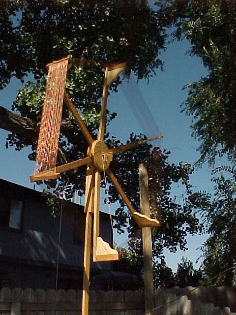
| Figure 4, Hexagon Loop This is the 1.5 meter hexagon loop, using 24 turns of #18 gauge braided copper wire. (Click on thumbnail to download full-size image) |
 |
This is how a friend [Joseph DiVerdi] and I tuned the1.5 meter hexagon loop to 25.2kHz. Just using two DMMs, and a Wien-Bridge oscillator, (built from Cap Hossfield's instructions in the Solar Bulletin, Vol. 58 No. 7, July 2002).
- We connected the 1st DMM to the hexagon loop between the start and ending [wires] of the loop, which terminate in the center circle, and set the DMM (Digital Multi Meter) to measure AC voltage.
- We then add some value of capacitance [1nf] and tried to create a resonant circuit and get a peak in the AC voltage. We could either specify an arbitrary value of capacitance or get closer by calculating the inductance of the coil and then calculating the approximate capacitance, using the ARRL handbook.
- Next, set the Wien-bridge oscillator and it's small copper loop close to the hexagon loop and slowly tuned the WB oscillator until there was a peak in the AC voltage of the first DMM at the hexagon loop. When the WB peaked the AC voltage, we had a good starting estimate of the correct capacitance for the 24-turn hexagon loop.
- We then attached the Wien-bridge to the second DMM to measure its frequency, which read about 27.7kHz. This indicated the 'natural' frequency of the hexagon loop or the resonant frequency of the coil-capacitor combination.
- Now we re-tuned the Wien-bridge to 25.2kHz, or the station of interest, using the 2nd DMM. Then put the WB and it's loop close to the hexagon and adjusted the capacitance of the hexagon loop to cause the resonant frequency to occur at the frequency of interest.
- We then hooked up the Gyrator II directly to the Wien-Bridge, i.e. no loop, just plug the oscillator right into the F connector at the back of the Gyrator, and tuned the Gyrator II. The 2nd DMM is there to measure the output of the Gyrator II in DC voltages. When the DMM peaked, around 4.56 volts, we marked this setting, as it should be the Gyrator's 25.2kHz setting. (We set the gain on the Gyrator II to about half.)
- Now we hooked the Gryator II to the hexagon loop, and kept the 2nd DMM measuring voltages at tbe back of the Gyrator II. (It may be preferable to tune the coil-capacitor without the Gyrator in this step.)
- With the 2nd DMM set to the DC output of the Gyrator II, now set the WB oscillator (tuned to 25.2kHz) and it's loop close to the hexagon loop and turn it on and watch the response of the Gyrator II as it records the output, WHILE you:
- Use the 1st DMM to measure capacitors, AS YOU ADD nano Farad capacitors, to get the 27.7kHz loop to tune to the 25.2kHz Gyrator II (we added ~ 40 nfd) capacitors attached to both ends of the hexagon loop. At some point the loop will peak the 2nd DMM output of the Gyrator II.
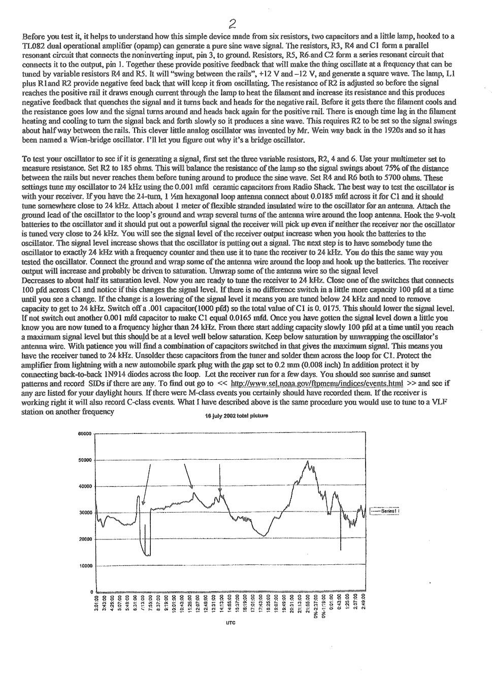
| Figure 5, Wien-Bridge schematic and parts list (Cap Hossfield, AAVSO, Vol 58, No 7, July, 2002)
(Click on thumbnail to download full-size image) |
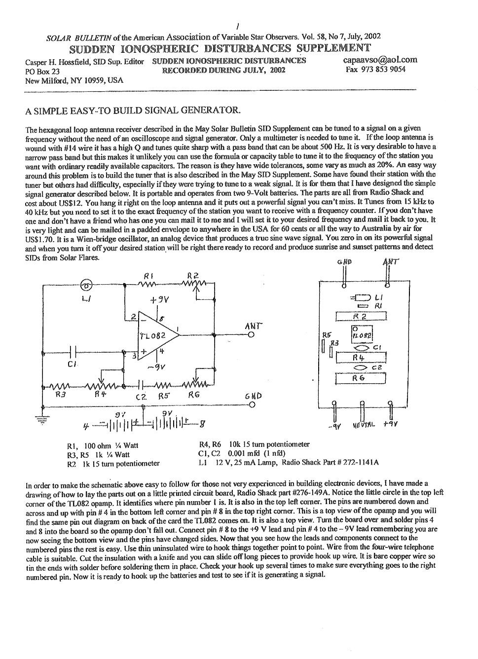 |
| Figure 6, Description of Wien-Bridge (Cap Hossfield, AAVSO, Vol 58, No 7, July, 2002)
(Click on thumbnail to download full-size image) |
 |